
Abstract
Recently, many videos of Xiaomi SU7 losing control have gone viral, with some claiming issues with traction control. This article focuses on explaining what traction control is.
During braking or acceleration, excessive braking or driving wheel slip can cause a vehicle to lose or significantly reduce control when one or more wheels exceed their stability limits. The renowned Anti-lock Braking System (ABS) addresses this by ensuring optimal stability, maneuverability, and braking distance during emergency stops. To maintain stability, maneuverability, and optimal traction during acceleration—especially on asymmetric road surfaces or during cornering—the Traction Control System (ASR) plays a critical role.
This article describes several methods for optimal traction control, such as regulating engine torque by adjusting throttle opening, ignition timing, and fuel injection. Beyond these vehicle stability approaches, it also explains methods to optimize traction on split-friction surfaces through braking force control of driving wheels or variable limited-slip differentials.
To ensure stability and maneuverability—particularly for manual transmission vehicles—closed-loop control of engine drag torque (MSR) serves as a valuable complement to ABS.
01 Introduction
With the increase in vehicle ownership and traffic density, the requirements for drivers to control vehicles have become more demanding. Therefore, significant efforts have been made to improve vehicle operability and driving performance. When driving, acceleration, steering, and braking form a closed-loop control system comprising the driver, vehicle, and environment (see Figure 1). The adhesion between tires and the road surface constitutes the primary connection between the vehicle and its environment.
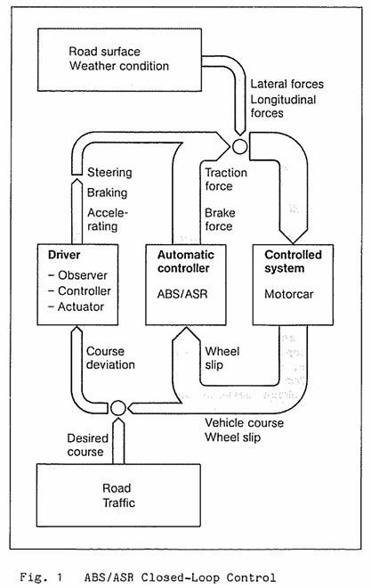
Only when the system composed of the vehicle and the environment is in a controllable state can the driver fulfill the function of its controller. If one or more wheels exceed the stability limit due to excessive wheel slip during braking or acceleration, the ability to drive the vehicle may be seriously impaired or even lost. Automatic control systems can react faster and more accurately than drivers, helping to maintain vehicle stability in situations where drivers might be overwhelmed.
02 Reasons for Introducing ASR
The goal of maintaining vehicle stability and maneuverability during braking has been increasingly achieved by the Anti-lock Braking System (ABS). The task of ensuring stability and maneuverability during acceleration is accomplished by ASR (Traction Control System). During acceleration, similar to braking, slip occurs between the tire and the road surface. The longitudinal and lateral forces that the tire can transmit also depend on positive or negative slip. These relationships can be described by the so-called friction circle. Therefore, the experience gained in the development of ABS can be applied to the development of ASR systems.
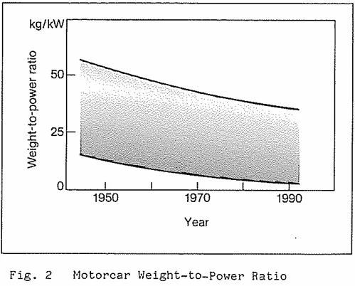
In the development of passenger vehicles, the power-to-weight ratio (weight-to-power ratio) has been continuously decreasing. Figure 2 shows the downward trend of vehicle mass relative to engine power over the past few decades, and this trend is likely to continue. As a result, drivers must operate the accelerator pedal more precisely under low road friction coefficient conditions, whether in rear-wheel drive or front-wheel drive mode. In rear-wheel drive vehicles with high-performance engines, careless acceleration or sudden release of the accelerator pedal may cause instability or skidding. In front-wheel drive vehicles, steering ability may be lost. The most important function of ASR (Traction Control System) is to automatically reduce engine torque to a level that can be transmitted to the road surface. ASR is also supplemented by MSR (Engine Drag Torque Control), which provides optimal engine drag torque during coasting operations.
2.1 Objectives
The objectives of ASR and MSR are:
- Improve driving convenience
- Ensure stability and maneuverability
- Enhance traction
- Provide drivers with road surface information
ASR and MSR together reduce the probability of tasks that drivers may fail to complete in emergency situations, even experienced drivers face considerable challenges in such scenarios. Automatic intervention ensures stability and maneuverability within the physical limits. In addition to acceleration and braking stability at high speeds, improving traction at low speeds has become increasingly important, such as initial acceleration under low friction coefficient conditions. In single-axle drive vehicles, ASR with a limited-slip differential can significantly enhance traction by automatically decelerating potentially slipping wheels, especially on roads with uneven friction coefficients. The requirements for stability/maneuverability and maximum traction are contradictory in some aspects, so compromises must be made. Typically, stability and maneuverability are prioritized. Signals generated by the automatic control system can also be used to provide drivers with optical or acoustic indications, prompting that the vehicle is approaching the physical stability limit.
03 Possible ASR Control Methods
The function of maintaining driving wheels within the optimal slip range can be achieved through several methods or their combinations:
- Adjusting engine torque
- Braking driving wheels
- Controlling limited-slip differentials
- Controlling the coupling between the engine and driving wheels
3.1 Engine Torque Adjustment
Controlling engine torque maximizes driving force transmitted to the road surface. Possible control methods include:
For spark-ignition engines, controlling the following aspects:
- Fuel injection
- Ignition timing
- Throttle position
From the perspectives of acceleration smoothness, engine load, and exhaust composition, throttle control is the most favorable intervention. Auxiliary control of fuel injection or ignition can compensate for the relatively slow response time of throttle control. Through ignition control, the ignition timing is delayed to reduce engine torque. If this is insufficient, ignition pulses are stopped. In this case, fuel injection must be halted to prevent excessive emissions or catalytic converter overload. Interrupting injection alone reacts slowly because the engine continues to inhale and burn the supplied fuel. Controlling only ignition or injection without throttle adjustment may suffice for low-performance vehicles.
For diesel engines, engine torque is adjusted by changing the fuel injection quantity. Due to its immediate impact on engine torque, the response time is sufficiently short. When releasing the accelerator pedal in low gears on low-friction surfaces, driving wheels may experience excessive braking slip. MSR prevents this by slightly increasing engine torque, reducing wheel braking effect to the optimal stability level.
3.2 Braking Driving Wheels
Applying braking pressure offers the shortest response time as it directly affects the slipping driving wheels. For smoothness, the buildup rate of braking pressure is slightly reduced to avoid potential maxima. In vehicles that control engine torque solely via throttle, braking control serves as a rapid supplementary means to ensure stability and maneuverability.
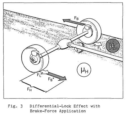
This control method also serves another important function: generating the effect of a limited-slip differential. Figure 3 shows the longitudinal forces acting on the driving wheels. A wheel on a high-friction road can transmit forceFHmax, while a wheel on a low-friction road can transmitFLmax. The differential only allows2×FLmaxforce to be transmitted to the road. To prevent wheel slip on low-friction roads under high engine torque, braking forceFBis applied. This enables maximum tractionFtot=FHmax+FLmax=2FLmax+FB∗, whereFB∗is derived from braking forceFBvia different effective radii. Engine torque is controlled based on maximum traction, during which brief braking may be applied to wheels on high-friction roads. For front-wheel drive vehicles with low-power engines, braking control on one or two driving wheels can assist with starting acceleration, though this must be time-limited and restricted to low speeds to avoid brake overheating.
3.3 Controlling Rear Axle Limited-Slip Differential
To achieve optimal braking, all vehicle wheels should operate independently when using ABS. Thus, fixed-value differential locks and so-called viscous locks, while improving traction, cannot maximize ABS functionality. From a physical perspective of driving and braking stability, limited-slip differentials with variable locking are superior solutions. The electronic control unit regulates wheel slip within allowable ranges by increasing, maintaining, or reducing hydraulic pressure in the limited-slip differential. Limited-slip differentials typically improve traction when driving wheels encounter varying friction coefficients. During acceleration from rest, a set locking degree enhances traction without compromising driving stability up to a certain speed. During low-gear cornering coasting, this control also increases stability: the locking effect drives the inner unloaded wheel of the curve via the outer wheel, preventing severe slip and loss of lateral force. Simultaneously, more engine drag torque is transmitted to the outer wheel, generating an axle torque that stabilizes oversteer.
3.4 Integrated Control Methods
The mentioned wheel slip control methods affect vehicle stability, maneuverability, and traction. For simplicity, methods with differential lock effects can be termed “traction control,” and those involving engine torque adjustment “stability control.” In principle, any combination of methods can be chosen to integrate both characteristics.
4 ASR Control Actuators
4.1 Throttle or Diesel Injection Pump Actuators
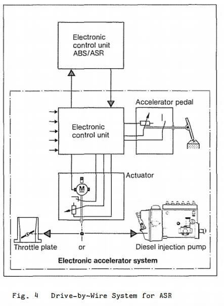
Throttles in spark-ignition engines are controlled electromechanically or electromagnetically. The actuator system called “electronic accelerator pedal” is shown in Figure 4. The driver’s command is converted into an electrical signal via a sensor on the accelerator pedal. The ECU transforms this signal into a control voltage for the electric actuator motor, considering preset variables and signals from other sensors (e.g., temperature, engine speed). The actuator motor moves the throttle or diesel injection pump control rod, with position feedback sent to the ECU. Execution commands from ASR (including MSR) override the driver’s instructions in the electronic accelerator pedal’s control unit. For example, if the driver fully opens the throttle, ASR can reduce the opening to 10° within ~100 ms. Under MSR commands, the throttle opens slightly from its actual position—e.g., ~10° from idle during coasting. The electronic accelerator pedal enables additional functions independent of ASR/MSR:
- Replace mechanical throttle linkage with reference to functional characteristic maps
- Speed control or limitation
- Idle control based on engine temperature and load
4.2 Electronic Ignition Control System
In modern electronic ignition systems, the ignition timing is set based on input variables such as engine speed, engine load, and coolant temperature. During ASR operation, a wheel slip signal causes the ignition timing to delay proportionally to the slip amount. If ignition delay is insufficient to reduce slip, or if slip continues to increase rapidly, ignition will be cut off. When ignition restarts, the timing moves from the delayed position to the optimal position via a ramp function, allowing engine torque to increase as slowly as possible. To prevent unacceptable exhaust emissions and avoid stress on the engine and exhaust system, fuel injection must be cut off during ignition interruption. Modern engine management systems like Bosch Motronic have greatly simplified fuel injection and ignition control.
4.3 Fuel Injection Systems for Spark-Ignition Engines
Electronically controlled fuel injection systems such as Bosch L-Jetronic and KE-Jetronic adjust fuel injection quantity based on various engine operating conditions. Air flow, engine speed, and temperature sensors are used for this purpose. ASR leverages these signals and control capabilities. Similar to fuel cut-off when closing the throttle at high speeds, ASR control signals also interrupt injection. When restarting injection, torque increase can be moderated by temporarily delaying ignition.
4.4 Fuel Injection Systems for Diesel Engines
Electronic diesel control realizes the driver’s intent through sensors on the accelerator pedal. The control unit processes this input using additional information (e.g., engine speed, temperature, boost pressure) and calculates output signals to control mechanical fuel injection pump components. In electronic diesel control, execution commands from ASR/MSR also take precedence.
4.5 Braking System
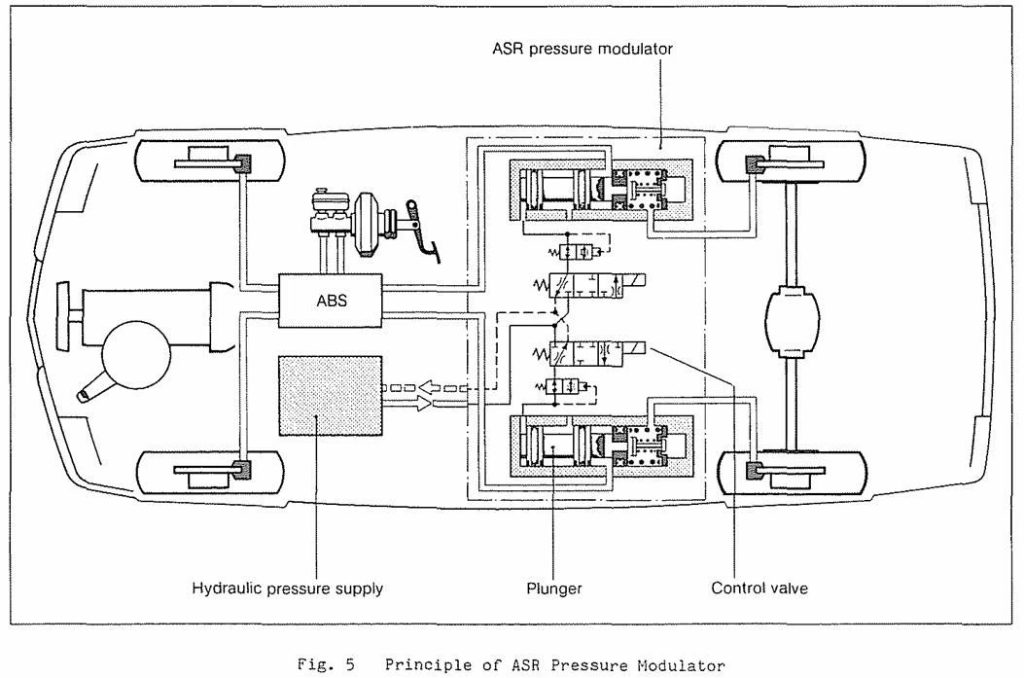
ASR braking force control is achieved by utilizing the existing functions of ABS components. Experience so far shows that ABS and ASR have different pressure build-up rates, especially for front-wheel drive vehicles requiring different valve throttle cross-sections. To ensure good control smoothness and minimal steering interference, ASR requires a slower pressure build-up rate than ABS. The working principle of the ASR 2 system based on the Bosch ABS 2 system is described in the literature. Correspondingly, the plunger design shown in Figure 5 can be used for automatic braking actuation. This configuration is suitable for integration with various ABS systems. Ideally, the existing ABS hydraulic system requires no modification, allowing significant flexibility in the installation position of the ASR system—particularly applicable when ASR is an optional configuration.
4.6 Brake Piston
Brake pistons are controlled by solenoid valves. During ASR operation, the pressure required by ASR is applied to the main side of the respective piston via a 3/3 solenoid valve. As the pressure pushes the piston toward the brake circuit, the central valve closes the connection to the master cylinder, enabling pressure build-up in the driving wheel brakes. Switching to a smaller throttle cross-section also offers further advantages in control quality and smoothness. The separation of two hydraulic media (brake fluid and mineral oil) is designed according to existing technology. During braking and ABS operation, the flow from the piston to the driving wheels remains unimpeded without significant throttling effects. If a vehicle already has a pressure-providing system—such as an automatic leveling control system—that can be shared with ASR, the above piston concept becomes particularly attractive and cost-effective. For low-power front-wheel drive vehicles, both electric and hydraulic actuator pistons are under consideration.
4.7 Controllable Limited-Slip Differential
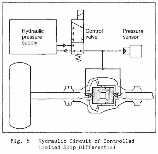
The locking ratio between driving wheels can be achieved via hydraulic preload discs in the differential gears. This locking ratio can continuously increase from a 10% base value to full lock. The required hydraulic pressure is provided by a pressure accumulator, with a 3/3 solenoid valve for pressure regulation. The hydraulic circuit is shown in Figure 6. Using a control pressure sensor can enhance control quality.
5.Comparison of Several ASR Systems
5.1 ASR with Engine Control
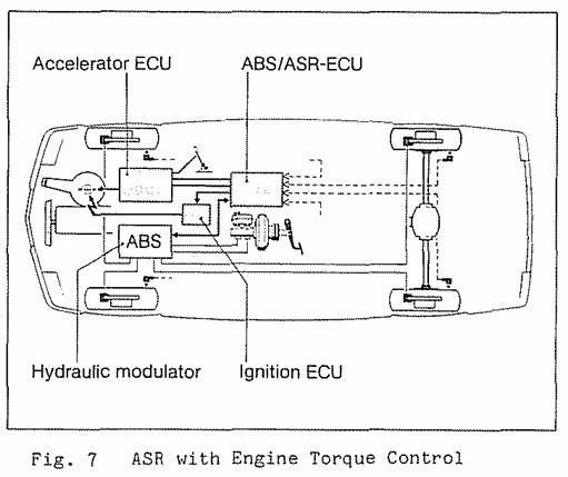
This system uses electronic throttle pedals, ignition, and injection systems for control. As shown in Figure 7, by rapidly matching engine torque to the force transmissible to the road surface, it provides smooth operation and high driving stability for rear-wheel drive vehicles, while offering good maneuverability for front-wheel drive vehicles. Traction is also improved on roads with uniform friction coefficients.
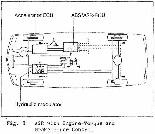
5.2 ASR with Engine and Braking Control
This system employs electronic throttle pedals and driving wheel braking systems for control (as illustrated in Figure 8). By generating a limited slip effect, it improves traction—particularly on roads with uneven friction coefficients—while enhancing stability and maneuverability through friction coefficient optimization.
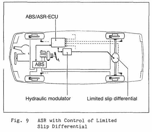
5.3 ASR with Controllable Limited-Slip Differential
This system (as shown in Figure 9) primarily serves as a traction assist device, especially suitable for roads with uneven friction coefficients. It offers significant advantages over previous types of differential locks: it does not negatively impact ABS functionality, can provide high locking effect when needed, and has no adverse effects during emergency cornering. Additionally, on high-friction surfaces, it improves driving stability during turns.
5.4 ASR with Engine and Controllable Limited-Slip Differential
This system integrates the advantages described in 4.1 and 4.3 above. It represents an effective solution in terms of stability, traction, and driving comfort.
5.5 Other Control Combinations
In principle, all the above control methods can be combined to achieve the optimal solution, balancing driving stability, maneuverability, traction, comfort, and overall system cost.
6.Special Considerations for Four-Wheel Drive
The use of four-wheel drive significantly simplifies vehicle driving, as the tire-road coupling range is broader compared to single-axle drive under the same engine power. However, regardless of the four-wheel drive design, ASR application can further enhance traction and cornering capability. During acceleration on low-friction surfaces, all four driving wheels may slip, making electronic simulation of vehicle speed for improved cornering performance more challenging. Simulation is achieved through complex calculations of possible vehicle acceleration derived from the current engine load (considering other vehicle parameters) or by measuring ground speed. Traction enhancement can be realized by controlling the braking system to generate a differential lock effect or via controllable limited-slip differential regulation.